This article has been reconstructed from the excellent Minolta SR-T site created by Dick Sullivan, which is unfortunately now no longer on the web. Our thanks and respects go to Dick Sullivan for his committment to other Minolta manual focus users.
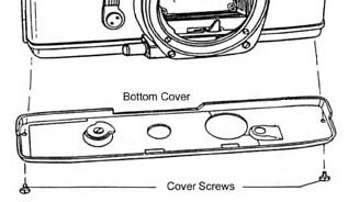
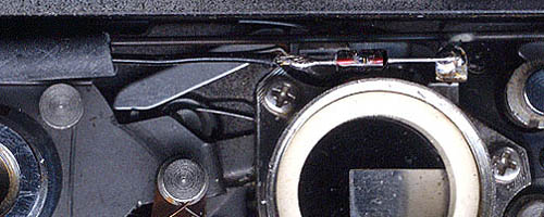
As described in the page about the Mercury Battery, many early cameras including the SRT were designed to operate on the now banned 1.35v mercury cell. In order to have the camera meter correctly with modern 1.5v cells the voltage of the cell must be reduced to 1.35v. Dick proposed that the easiest way to do this was to convert the SRT through the use of a Schottky diode. The conversion has been conducted and does work very well, reducing the voltage to the camera meter circuit to 1.35v. The conversion requires simple tools, some soldering skills, and the removal of the camera's bottom cover. Overall it takes about one hour.
![]()
- A No. "0" Phillips Jewelers Screwdriver.
- A Small Soldering Iron with a pointed tip, 25 Watts or so.
- A 1N5711 Schottky Diode.
- A short (about 2") piece of insulating plastic tubing, with an 1/8" inside diameter.
- A short length of small gauge 60/40 solder.
- A Fresh '76
1.5 volt Silver Oxide Cell:
- Duracell® MS76H
- Kodak® KS76
- Varta® V76PX
- Panasonic® SP76
- Rayovac® RS76
- Energizer® EPX76 or 357
- Either a Plastic Adapter Ring, or a # 111 Rubber "O" Ring measuring approximately 5/8" outside dia. and 7/16" inside dia.

Any forward biased diode will drop a certain amount of voltage depending on its type, construction, the current flowing through it and to some extent, its temperature. The type and construction of a diode used is the major factor in the amount of forward voltage drop it has. For instance, a Germanium diode will typically drop .4 volts or more and a Silicon diode will drop about .6 Volts, neither of these types will suit our needs. Since a Silver Oxide Cell delivers about 1.6 volts and a Mercury Cell reads about 1.35 volts we need a voltage drop of about .25 volts. It turns out that a forward biased 1N5711 Silicon Schottky Diode will drop the required .25 volts at the current range (10 ~ 200ua.) of the SRT metering circuit.
While temperature will affect this voltage drop a little, the effect will be extremely small at the temperature range of the camera in normal use. Photography in Antarctica or the Sahara Desert might be another story, but the mechanically operated SRT will likely have other problems long before those extreme temperature can cause any appreciable exposure errors. Temperatures of about 32º to 95º F, should be just fine. From my measurements at room temperature, the 1N5711 Schottky Diode was "spot on", reading a .25 volts drop, thus delivering 1.35 volts the SRT's metering circuit, perfect for our application. Other Schottky Diodes (1N6263, BAT41, BAT81, BAT82, BAT83) have a similar type and construction but I have not tested them.
Caution: The handling of the diode, as with any semiconductor requires certain precautions to prevent damaging it. You should protect it from static discharges and excessive heat. Before touching the diode leads be sure to ground yourself to a grounded metal surface to discharge any build up of static on your body. When soldering the diode, try to limit the time of heating to about 2 seconds.